|
|
||
|---|---|---|
| LICENSE | ||
| Nerfgun Controller 3 Button_Schaltplan.png | ||
| Nerfgun Controller_Schaltplan.png | ||
| Nerfgun-Controller-3Button.ino | ||
| Nerfgun-Controller.ino | ||
| README.md | ||
README.md
Nerfgun Controller Mod
Attiny45/85 firmware to control a laserpointer and high performance LED for a nerfgun
nerfgun-controller
I modded a laser pointer module and a bright LED on my nerfgun, added two pushbuttons to the grip and screwed a battery box to the side. Per default the battery box can hold 3 AA batteries. I removed one spring holder and reduced the capacity to two AA batteries which gave me space for a small circuit board containing a Atmel Attiny45, some resistors and two PN2222 NPN transistors to control the LED and laser (the Attiny can provide only about 10mA per output pin which is not enough to power my equipment but it is more than sufficient to switch the NPN transistors).
This little program reads inputs from the two pushbuttons, debounces them and controls the laser (one push = on, next push = off and so on) and the LED (one push = on, next push = random strobe mode, next push = off). When laser and LED are off, the program configures pinchange-interrupts for the two push buttons and put the microcontroller to sleep. You can wake it up by pushing a button (which will activate LED or laser, whatever you've pushed). My battery box has an on/off switch but I keep forgetting to switch it off. While the microcontroller is running and waiting for a button push, it pulls about 4mA continously until the battery runs dry. When it puts itself to sleep waiting for the next button push, it pulls below 100uA (which is the smallest current my multimeter can measure).
This is the circuit I used for this 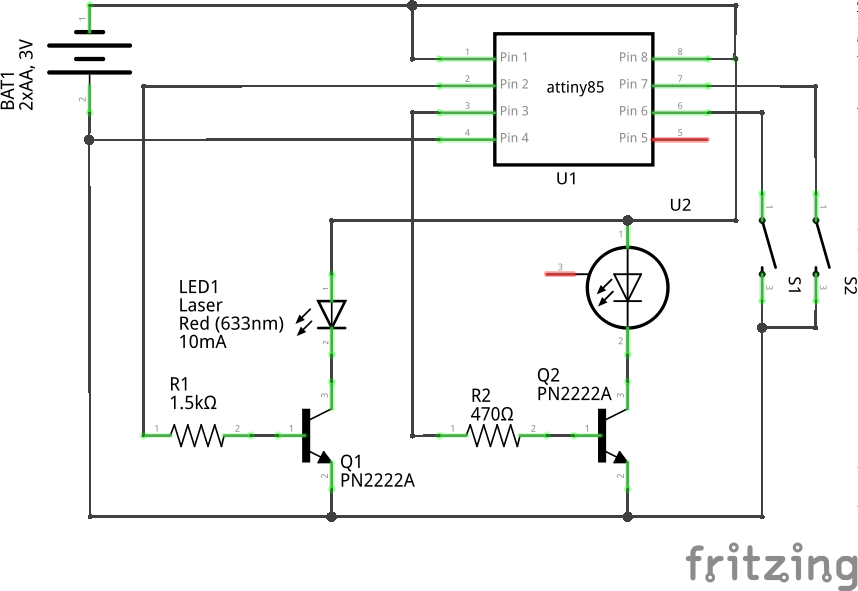
The program as it is now will not run on a Attiny25. It compiles to a binary containing 2092 bytes, the Attiny25 can store only 2048 bytes. I'm pretty sure you can optimize the code some more to free the necessary 44 bytes, but if it has to be quick and dirty, remove the sleep mode code and the includes for interrupt.h and sleep.h. That should reduce the code enough (although it means that your circuit will always draw power for the non-sleeping Attiny).
nerfgun-controller-3button
This is the 3 Button version of the controller. In the original design, I left one IO port unused and a friend of mine asked to add another button. One button switches the laser on and off while another button switches the LED on and off. The third button is a tactical button. If you push it and hold it pressed the following happens until you let go:
- If the LED is currently off, then the LED will go into strobe mode.
- If the LED is currently on, then it will go off.
The idea behind this is to make strobe mode quickly accessible (when you don't use the LED as flashlight) and have a quick way to temporarely switch off the LED when approaching a corner for example. Downside is that when you use the LED as flashlight, you cannot go directly into strobe mode but have to switch it off first. I think this is no real problem since you can also use the flashlight mode to blind your opponent or manually strobe the LED mashing the tactic button, but this has to be verified in battle first.
This is the circuit I used for this 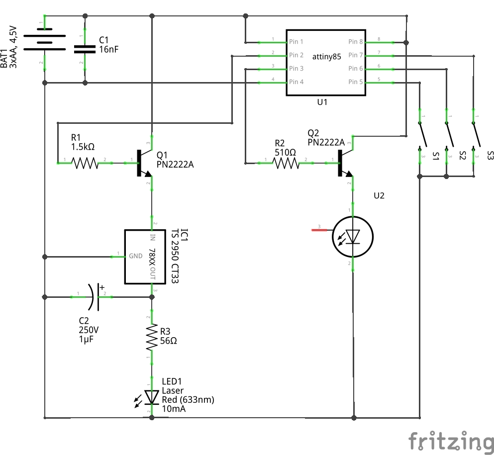
Like the original two-button solution, you need at least an Attiny45 for this, too. But since the push button handling for Light and Laser are simpler here, you can downsize it by removing the btnFlash object in setup() and removing the two IF blocks using it in its conditions. This will effectively take away the tactical button ability (and the strobe mode) but the resulting binary will be small enough to run even on an Attiny25 and you will keep the sleep mode which significantly lowers the drain on your battery.
General Troubleshooting
The strobe mode is kinda noisy. If you ever notice that your circuit behaves unusual, it could be that the strobe mode switching the LED off drops enough interference to Vcc to send your Attiny into reset state. In my case Strobe seemed inaccessible and also turned off the Laser (due to the reset). If that happens you can fix this by adding a small capacitor between the reset pin and ground. In my case 10nF was not enough but 16nF did the trick.
You probably noticed that I drive the LED in both circuits without a current limiting resistor. This is usually not a good aproach since LEDs get hot when you put current on them and when they get warmer their resistance will get lower (allowing more current to go through them which makes them hotter even faster). But in this case I have reasons to do this. In the 2 Button circuit I use two AA Batteries (3V). The forward voltage of the LED I used is 3.6V which means that the diode will not run fully free and so limit itself to a certain current. In my case about 60mA. They can handle 350mA. As long as I can't get more than 3V out of two AA batteries, this will limit itself to safe values. Yes, I could add a small resistor to it but that will make the LED darker so why should I do this?
In the 3 Button circuit I have three AA batteries for power supply which give me 4.5V. In this case the LED will draw more current, get hot fast and burn up. So I calculated the NPN transistors base resistor to a value that will only let about 160mA flow from collector to emitter. During my tests the LED will start at 156mA and as it gets hotter it will draw more current (the increase is about 0.3mA per second) until it hit the upper value the transistor can supply with that base current the base resistor allows. In my test it stopped increasing at about 160.3mA which is less than half of the maximum 350mA the LED can handle.
What does this mean for you? Read your LEDs datasheet. If you use some other NPN transistor, read its datasheet as well. It could be that you have to experiment with other base resistors. Choose a high value and go smaller from there. Or calculate the I(ce) current from the values on the datasheet. Bottom line: Everything depends on your power supply voltage and your parts. For example: Since my 3 Button solution provides 4.5V but my laser module is designed for 3.3V I had to add a voltage regulator to drive it safely. You can also add a voltage divider using two resistors but that will just drain the full power from the battery and transform the leftover power into heat. The power regulator will switch the imput power on and off which will result in a lower output voltage without using more power than necessary. On the other hand this will generate noise on the circuit, that is what the capacitors on the regulators output and on the reset line are for.
Thanks to
A big thank you to Thomas Ouellet Fredericks for his Bounce2 library (https://github.com/thomasfredericks/Bounce2) which I use in this project. That one is a great piece of software I use in almost all of my projects.
Also thank you to my amazing friends who made me buying Nerf guns so that I can shoot them with a whole crapload of foam darts. :)
Finally thank you to my son who made me remember that I received basic electronics knowlede two decades ago at school and made me experimenting with it to gather more knowledge. He did so by just being born into this world so that years from now, when he is older, I can build awesome things together with him.
ToDo
- Clean up the code a little bit
- Find a good solution for variating pin layout
- Maybe create an object from all of this that can be initiated with pin functions
- Longpress capability would be nice. Probably this comes with the next Bounce2 library?
- Fix imported README.md from Github